Gas chromatography (lab, micro, and field GC)
Summary
Section titled “Summary”Every other technology in this wiki is a sensor: a physical device that sits in a gas stream and continuously outputs a signal related to how much hydrogen is present. Gas chromatography (GC) is different: it is a laboratory method for taking a gas sample apart.
A small plug of gas is pushed by a flowing carrier gas through a long, narrow tube (the column) whose inner surface or packing material holds on to different gas molecules by different amounts; because they get held up by different degrees, the molecules exit the far end of the tube at different times, arriving one species at a time at a detector instead of all at once.
This time-separation is what lets a GC tell hydrogen apart from helium, methane, carbon monoxide, and everything else in a soil-gas or wellsite sample with near-total confidence, which no single continuous sensor elsewhere in this wiki can do at trace level. The tradeoff is duty cycle and complexity: a GC analysis takes minutes, not milliseconds, needs a carrier gas cylinder and (for the best hydrogen results) a specialized detector, and is not something that can simply be dropped down a borehole.
For Hestia, GC — specifically GC paired with a hydrogen-selective detector — is the reference instrument that tells you whether a borderline field reading is a real geologic anomaly or noise, not the tool that surveys a wide area quickly.
At a glance — published performance envelope
- Detection limit
- 0.0008–100 ppm
- Range
- 0.0008–1,000,000 ppm
- Response t90
- 15–1,800 s
- Recovery
- 30–1,800 s
- Selectivity
- high
- Drift
- low
- Operating T
- −10 … 45 °C
- Humidity
- 0–95 % RH
- Power
- 15–1,000 W
- Unit cost
- $1.7k–$50k
- TRL
- 9
Main interferents: carrier gas identity, He, H2O vapor, CO₂ · poisons: HgO reagent bed depletion in RGD, column stationary-phase degradation from water and high-boiling contaminants, carrier-gas impurities in PDHID service. Ranges span the published devices/variants covered below — per-claim citations are in the body; data: src/data/modalities/gas-chromatography.yaml.
Mechanism & physics
Section titled “Mechanism & physics”Why a separation method belongs in a sensor wiki
Section titled “Why a separation method belongs in a sensor wiki”Every other dossier in this wiki describes a transducer that responds to gas composition continuously and non-specifically (or semi-specifically). GC is an analytical method rather than a transducer. A gas chromatograph separates a mixture in time by exploiting differential partitioning between a mobile phase (the carrier gas) and a stationary phase (a packed sorbent or a capillary wall coating), then routes the temporally separated bands past a detector one at a time.
The detector itself is very often one of the other physical mechanisms covered elsewhere in this wiki — a thermal-conductivity cell akin to thermal-conductivity & acoustic sensors, a flame-ionization cell, a photoionization cell — but bolting a column in front of it converts a bulk-property, cross-sensitive sensor into a chemically resolved, quantitatively calibrated instrument. This is the reason GC gets its own page: the column does the selectivity work that the detector cannot do alone, and understanding that division of labor is central to using GC correctly for H2.
Retention and separation theory
Section titled “Retention and separation theory”A species with true (unretained) transit time through the column and enhanced retention on the stationary phase elutes at retention time . The retention factor
quantifies how strongly a species partitions into the stationary phase; depends on the phase-distribution (partition or adsorption) equilibrium constant and the phase ratio (mobile-phase volume / stationary-phase volume) as .
For adsorptive stationary phases like molecular sieves — the dominant case for permanent-gas GC (see Variants, below) — is governed by size- and polarity-selective physisorption into zeolite pores rather than bulk-liquid partitioning, which is why molecular-sieve GC can separate species (O2, N2, CH4, H2, CO) with almost no boiling-point difference; ordinary partition GC could not resolve them at all.
Band broadening as a species migrates is described by the van Deemter equation, relating the height equivalent to a theoretical plate (HETP, ) to the mobile-phase linear velocity :
where is eddy diffusion/flow-path heterogeneity (packed columns only; for open-tubular capillaries), is longitudinal molecular diffusion, and is the resistance-to-mass-transfer term between phases [36]. Solving for the minimum gives an optimum velocity , at which plate height — and hence peak sharpness and detection limit — is maximized. This is why a field-portable GC cannot simply “run faster” to shorten cycle time for free: pushing above trades cycle time for resolution and sensitivity, a recurring design constraint in every micro-GC method discussed below.
Two co-eluting or partially-resolved peaks are separated with resolution
( = baseline peak width). is the conventional baseline-resolution threshold. This matters for H2: on a molecular-sieve 5A column, H2 elutes very close to the column void volume alongside He and Ne, so short/fast micro-GC methods that shave cycle time by shortening the column risk losing between H2 and He precisely when both are analytes of exploration interest (see the “He co-measurement synergy” in Variants, below).
The thermal-conductivity detector (TCD/katharometer): governing physics and the H2–He anomaly
Section titled “The thermal-conductivity detector (TCD/katharometer): governing physics and the H2–He anomaly”The TCD is the default universal GC detector and the physical mechanism most directly shared with the standalone thermal-conductivity & acoustic sensors covered elsewhere in this wiki. A heated filament (or MEMS membrane) sits in a flowing stream of pure carrier gas; its steady-state temperature is set by the balance
between resistive heating and conductive heat loss to the gas, with heat-transfer coefficient an increasing function of the surrounding gas’s thermal conductivity . A Wheatstone-bridge circuit compares a filament bathed in pure carrier (reference arm) against one exposed to column effluent (sample arm); when an analyte band with different from the carrier passes, the sample-arm filament’s temperature — and hence resistance — shifts, unbalancing the bridge and producing a peak proportional (to first order) to [37].
Because every compound, organic or inorganic, has some thermal conductivity distinct from most carrier gases, the TCD is universal — it shows a peak for anything, including permanent gases (H2, O2, N2, CO, CO2, noble gases) that flame- and photoionization-based detectors cannot see. This universality is also its principal weakness: it cannot discriminate chemically at all; all discrimination comes from the column’s retention time.
Why He carrier is the wrong choice for H2, quantitatively. TCD sensitivity scales with the contrast between analyte and carrier thermal conductivity. NIST reference values (at 100 kPa, 300 K) give, in mW·m⁻¹·K⁻¹ [34][35]:
| Gas | Thermal conductivity (mW·m⁻¹·K⁻¹) |
|---|---|
| H2 | 186.6 |
| He | 155.7 |
| N2 | 26.0 |
| Ar | 17.7 |
| air | ≈26.4 |
The H2/He contrast is only , whereas the H2/N2 contrast is and H2/Ar is .
A carrier roughly an order of magnitude less thermally conductive than H2 (N2 or Ar) therefore gives 7–10× the raw bridge-imbalance signal per unit H2 concentration compared with a He carrier — except the cost runs the other way: switching carrier from He to Ar or N2 to fix the H2 measurement costs sensitivity on every other analyte in the run, because their conductivities are all much closer to Ar/N2 than to He, by a directly measured factor of 5–10× in at least one head-to-head Agilent Micro GC comparison [6][7][8].
The peak-inversion/non-monotonicity problem. A further issue beyond reduced contrast is genuine non-monotonicity: real gas mixtures do not mix their thermal conductivities linearly. The composition dependence of a binary mixture’s conductivity is well described by the semi-empirical Wassiljewa equation,
with the interaction coefficients (in the Mason–Saxena form) computed from pure-component viscosities, molar masses, and a polarity/Eucken correction [38]. For the H2–He pair specifically, the coefficients push below pure He’s value over roughly the 0–8 mol% H2 range before crossing back above it at higher H2 content — the mixture’s conductivity is genuinely non-monotonic in composition, not just weakly nonlinear.
In a TCD chromatogram this manifests as the classic “W”- or “S”-shaped H2 peak: as H2 concentration rises through the detector cell during elution, the signal first goes one way, crosses zero, and then reverses sign, so simple peak-height or even naive peak-area integration becomes unreliable once injected H2 approaches the percent level with He carrier [4][5]. Multiple independent studies confirm the practical fallout: HayeSep D / He-carrier TCD calibrations show piecewise, not single, linear ranges (e.g., 6–32.5% and 32.5–66.9% H2 as two separate linear segments in one 1998 study, with the break point itself shifting with sample size and oven temperature) [5].
The standard fix is either to swap the carrier to Ar or N2 (accepting the sensitivity cost above for co-analytes) or to run a mixed carrier gas — typically ~8.5–10% H2 in He — which pre-loads the detector’s reference arm above the inversion point so H2 analyte always produces a consistently signed (negative) peak; this restores good linearity ( up to 50% H2 in one validated method) while preserving most of He carrier’s benefits for other permanent gases, at the cost of consuming a specialty, single-source carrier-gas blend and the safety/logistics overhead of shipping compressed H2/He mixtures to a field site [6][7][8].
The reduction gas detector (RGD/RCP): HgO photometric chemistry
Section titled “The reduction gas detector (RGD/RCP): HgO photometric chemistry”The reduction gas detector — commercialized as the “RGD” by Trace Analytical/AMETEK and SRI Instruments, and rebranded “RCP” (Reducing Compound Photometer) by Peak Laboratories — is a chemically selective detector purpose-built for the small family of “reducing” gases: H2, CO, and a handful of unsaturated/oxygenated organics (ethylene, acetylene, formaldehyde). The reduction-gas/HgO-photometric principle is old enough to carry its own patent lineage (US4,411,867, “Reduction gas detector”) [39]. Column effluent passes through a heated bed (~250 °C) of mercuric oxide (HgO) supported on quartz wool; any reducing gas reacts stoichiometrically,
liberating gaseous elemental mercury. The Hg vapor is swept into a heated (~180 °C, to prevent condensation) UV absorption cell where a low-pressure Hg lamp emits at 253.7 nm — the resonance line most strongly absorbed by ground-state Hg⁰ vapor itself — and a photodiode measures the transmittance drop, approximately proportional to Hg vapor concentration and hence to the mass of reducing gas that reacted [1].
Two features give this mechanism its high sensitivity: each reacting H2 or CO molecule liberates one Hg atom, and Hg’s UV absorption cross-section at 253.7 nm is very large (the same physics behind Hg-vapor leak detectors); and the reaction is essentially specific to reducing species — the vast majority of soil/atmospheric gas (N2, O2, Ar, CO2, CH4) passes through the hot HgO bed unreacted and produces no signal.
SRI’s operating instructions demonstrate this sensitivity directly: an SRI RGD, run on a 2 m molecular-sieve 5A column with He carrier, resolves 500 ppb ambient hydrogen from a 1 mL injection of ordinary room air on an as-shipped, non-optimized bench setup [1]. The RGD therefore detects H2 below the 0.53 ppm tropospheric background in a single grab-sample injection with no preconcentration, which no other detector class in this wiki can do without additional preconcentration or averaging.
Pulsed-discharge helium ionization detection (PDHID/PDD)
Section titled “Pulsed-discharge helium ionization detection (PDHID/PDD)”The PDHID (marketed by VICI/Valco as the “D-2”/“D-4” series pulsed discharge detector, and used inside several field GCs) replaces the radioactive ⁶³Ni source of a classical electron-capture detector with a stable, low-power pulsed DC electrical discharge struck in a small volume of ultra-pure helium [16]. The discharge creates helium atoms in long-lived metastable excited states (He* at 19.8 and 20.6 eV) and emits VUV photons; both channels can photoionize essentially any eluting molecule, because 19.8–20.6 eV exceeds the first ionization potential of virtually every permanent gas and organic compound [16][18]:
| Species | First ionization potential |
|---|---|
| H2 | 15.4 eV |
| N2 | 15.6 eV |
| O2 | 12.1 eV |
| CO | 14.0 eV |
The resulting ion/electron pairs are swept to a bias/collector electrode pair and measured as current, giving a universal, non-radioactive, non-destructive detector with response across essentially all permanent gases. Because ionization occurs in the gas phase from a photon/metastable flux rather than from combustion chemistry, PDHID sensitivity is set by photoionization cross-section and background electron/ion noise, not by carrier-gas thermal-conductivity contrast — it does not suffer the He/H2 TCD peak-inversion problem, and is normally run on pure-He carrier specifically to maximize the metastable/VUV photon flux.
Published detection limits for H2 by PDHID are in the low-ppb range in dedicated GC-PDHID systems and ~0.3 ppmv in breath-analysis configurations optimized for speed over ultimate sensitivity [17][18]; NOAA’s atmospheric monitoring network adopted a GC-He-pulsed-discharge-detector (GC-HePDD) method in 2009 specifically because it gave a stable, linear response across the 0–2000 ppb range, replacing an RGA/HgO method whose response was “nonlinear and required frequent calibration” [19].
Why FID is structurally blind to H2
Section titled “Why FID is structurally blind to H2”The flame-ionization detector (FID) burns column effluent in a small H2/air diffusion flame and measures the ion current produced when carbon-containing pyrolysis fragments (principally CHO⁺) are formed and collected at a biased electrode. The FID is, by construction, a carbon counter: response is proportional to the number of C–C and C–H bonds capable of forming these ions, with essentially zero response to fully inorganic species (H2, N2, O2, CO2, H2O, noble gases) because they contain no carbon to ionize in the flame chemistry [20][21].
Variants & subtypes
Section titled “Variants & subtypes”GC “for H2” is a three-axis design space — instrument class, column chemistry, and detector — and the exploration-relevant configurations sit at specific, well-defined points in that space.
Instrument class
Section titled “Instrument class”- Lab/bench GC — full-size, line-powered, packed- or capillary-column instruments (Agilent 8890/7890 series, SRI 8610C/8610D on a bench, AMETEK/Trace Analytical ta3000/ta5000 process analyzers). Largest column choice, highest achievable resolution, can host several detectors in series or parallel, but requires AC power and a cylinder gas supply — though SRI explicitly markets the 8610C as small enough to check as airline luggage [13].
- Micro-GC — MEMS/chip-scale instruments (Agilent 990 Micro GC, INFICON Micro GC Fusion) using short (meters, not tens of meters) molecular-sieve or PLOT modules, micro-machined injectors with millisecond-scale sample plugs, and a micro-TCD (µTCD) with a cell volume of tens of nanoliters rather than the ~100 µL+ of a conventional TCD. Cycle times fall to 1.5–3 minutes for full permanent-gas panels [10][11], and the whole instrument can be battery/cylinder-powered in a field case for genuinely portable, quasi-continuous deployment [12].
- Field-portable “briefcase” GC — full packed/capillary-column architecture shrunk into a rugged, shippable chassis (SRI 8610C/8610D/310, up to six detectors and five injectors, oven programmable ambient–400 °C) [13]. These retain nearly all of the flexibility of a bench GC — any packed or capillary column, any of ~16 detector types including TCD, FID, RGD, and SRI’s own HID (helium ionization) design — while being genuinely field-deployable.
- Online/continuous process/environmental GC — fixed, weatherized cabinet instruments designed for unattended, cyclic (not truly continuous) operation at a single site: AMETEK’s ta3000R/ta5000R reduction-gas analyzers, Chromatotec’s Auto-GC 866 range (ChromaTCD, Chroma DID) — repeating an injection/separation/detection cycle every few minutes for weeks to months, typically installed in a fixed enclosure rather than carried between soil-gas stations [3][30][31].
Column chemistry for permanent gases
Section titled “Column chemistry for permanent gases”- Molecular sieve 5A — a calcium aluminosilicate zeolite with ~0.5 nm effective pore diameter (unverified). Provides the strongest retention and best separation of Ar/O2/N2 among common packings, making it the standard choice for trace-impurity analysis in inert/noble carrier gases and for resolving H2 from He/Ne near the column void (unverified) [22].
- Molecular sieve 13X — a sodium aluminosilicate with ~1 nm pores (unverified); lower retention than 5A, giving sharper (less tailed) peaks and better trace-CO detection limits, at some cost to Ar/O2/N2 resolution [22].
- PLOT (porous-layer open-tubular) columns, including Mol Sieve 5A PLOT capillaries — an open-tubular capillary with the sieve material coated as a thin porous layer on the inner wall rather than packed as beads. PLOT columns give much higher plate counts, faster analyses, and sharper peaks for fixed gases and light hydrocarbons than packed columns, and are reported to be the dominant column format inside modern micro-GC modules (unverified) [22].
- A caveat specific to molecular sieves: they are also excellent desiccants. Water vapor is strongly and often semi-irreversibly retained on 5A/13X sieve surfaces, progressively degrading retention reproducibility and requiring periodic high-temperature bake-out/reconditioning; virtually every soil-gas or wellsite GC front-end therefore needs an upstream drying stage (a Nafion membrane dryer is the standard choice) before the sieve column, which introduces its own selective-loss risk (see Environmental covariance, below).
Detector ladder, summarized
Section titled “Detector ladder, summarized”- TCD/katharometer — universal, non-destructive, ~10–100 ppm-class LOD for H2 depending on carrier and cell design; the only detector that can co-detect essentially everything, at the cost of the He-carrier peak-inversion problem above.
- RGD/RCP (HgO reduction–UV photometric) — the ppb-class workhorse for H2 and CO specifically; essentially blind to the bulk matrix gases, at the cost of a consumable HgO bed, a small elemental-mercury waste stream, and no response to any non-reducing species [1][2][3].
- PDHID/PDD (pulsed-discharge helium ionization) — universal, non-radioactive, ppb-class LOD across the whole permanent-gas suite, immune to the He/H2 TCD crossover, and increasingly the detector of choice for atmospheric-reference-grade H2 work (it is what NOAA’s flask network uses today) [16]–[19].
- FID (flame ionization) — included only to be ruled out: zero response to H2 by mechanism; useful on the same instrument only for co-eluting hydrocarbons.
- Other detectors seen in exploration-adjacent GC systems but not H2-relevant: ECD (electron capture, halogenated species), FPD/PFPD (flame photometric, sulfur/phosphorus — relevant to co-measuring H2S), PID (photoionization, aromatics/VOCs) [13].
Carrier-gas variants and the He co-measurement synergy
Section titled “Carrier-gas variants and the He co-measurement synergy”Three carrier-gas configurations trade off differently:
- Pure He carrier gives the best overall column efficiency (low viscosity, favorable diffusivity) and is the default for most permanent-gas methods, but triggers the H2 TCD inversion problem above.
- Pure Ar or N2 carrier removes the H2 TCD non-monotonicity entirely at the quantified 5–10× sensitivity cost for other analytes discussed above [6][7][8].
- A mixed 8.5–10% H2-in-He carrier restores good H2 linearity on a He-based method by pre-biasing the bridge past the inversion point, at the cost of a nonstandard carrier-gas supply chain [6][7][8].
Modern micro-GCs solve this differently, by running different carrier gases on different modules of the same instrument simultaneously: the INFICON Fusion’s Hydrogen-in-Natural-Gas method runs the Molsieve module on Ar (optimized for a clean, non-inverted H2 peak) while the Q-Bond module runs on He (optimized for hydrocarbon sensitivity), giving “best sensitivity for hydrogen and the other natural gas components” without the classic tradeoff [7][8].
Because H2, He, and Ne all elute very close together near the void volume of a molecular-sieve column, and because He is itself a first-order geologic-hydrogen exploration target (elevated He is a well-known companion anomaly to natural H2 seeps), the same mol-sieve channel that resolves H2 can, with adequate column length/backflush timing, simultaneously quantify He — a direct instrumentation synergy that lets one micro-GC channel deliver two of the highest-value exploration gases from a single injection, provided the method is validated for baseline resolution between H2, He, and Ne rather than optimized for H2 speed alone [10][11][22].
See geologic context for why He co-measurement matters so much to a seep-hunting program.
Performance envelope
Section titled “Performance envelope”| Parameter | Lab GC–TCD | Micro-GC–µTCD | Field portable GC (SRI 8610C-class) | GC–RGD/RCP | GC–PDHID |
|---|---|---|---|---|---|
| H2 LOD | ~10–100 ppm (bulk-gas methods) [13][37] | ~1 ppm, “≥10× more sensitive than traditional TCD” per vendor [9] | ~100 ppm (TCD channel) [13] | 25 ppb (bulk-gas, factory-certified) down to 800 ppt (optimized RCP method) [2][3] | low-ppb range; NOAA network stable/linear 0–2000 ppb [17][19] |
| Useful range | ppm to 100 vol% | ppm to 100 vol% (e.g., 10% H2-in-natural-gas validated method) [8] | ppm to 100 vol% | 0–3 ppm as shipped; higher optional [3] | ppb to several thousand ppm |
| Cycle/analysis time | 5–30+ min (packed column, full permanent-gas panel) | 1.5–3 min per channel [11] | 2–10 min typical (method-dependent) | 2–10 min (application-dependent; 2 min for dissolved-H2-in-water method) [3] | minutes (shares GC cycle time of host instrument) |
| Selectivity | High (via retention time), but detector itself is a non-specific bulk-property sensor | Same | Same | Very high — near-specific to reducing gases (H2, CO, light unsaturates) [1][20] | High — universal ionization, resolved by retention time like TCD |
| Carrier-gas consumption | Cylinder-fed, no inherent limit; typically tens of mL/min | ~1–4 cc/min per channel; a standard He tank can last “1.5–2 years” in continuous micro-GC duty [8] | Cylinder or on-board gas modules | 20–100 sccm sample flow, cylinder carrier [3] | Ultra-high-purity He required; consumption similar to TCD-class instruments |
| Power | Line power, oven can draw significant transient power during ramps | ~180 W max (12 VDC) [12] | Line power (110/220 VAC) [13] | 100–240 VAC line power [3] | Similar to host GC; PDD module itself is low-power (mA-class discharge) |
| Weight/form factor | Bench instrument, tens of kg | Benchtop or field-case (2 batteries + 2×150 mL/124-bar gas modules, ~16 h autonomy) [12] | ~18.5”×14.5”×12.5” mainframe, field-shippable [13] | 35 lb / 15.9 kg chassis, 7”×16.8”×26.5” [3] | Add-on module to host GC |
| Cost class (instrument) | Mainframe from ~$8,944–12,235 (SRI 8610C/8610D bare chassis) [14] | Multi-thousand to tens of thousands $, module-dependent | Configured system $16,000–$32,600 (SRI TCD/HID multi-gas or mud-logging methods) [14] | Detector add-on $5,810 (bare RGD, SRI); full ta3000R-class process analyzer typically tens of thousands $ [14] | Detector add-on ~$4,738 (SRI HID design) to $7,116 (chassis-mounted) [14] |
| Ambient operating T (instrument) | Typically 10–32 °C per process-analyzer spec (ta3000R) [3]; wider for ruggedized field units | Vendor-dependent, generally lab/vehicle-cab range | Rated for field/outdoor use; exact ambient limits not independently confirmed | 10–32 °C (ta3000R factory spec) [3] | Shares host GC’s ambient rating |
| Drift/lifetime | Low with routine calibration; TCD filaments and RGD HgO beds are consumables with finite life | Same | Same | HgO bed depletes with cumulative reducing-gas load and needs periodic replacement; non-linear response “required frequent calibration” in NOAA’s pre-2009 configuration [19] | PDD electrodes/discharge cell are long-lived relative to combustion-based detectors; requires ultra-pure He to avoid drift from carrier impurities |
The carrier-gas sensitivity tradeoff, restated as a method-selection rule. Holding column and injection volume fixed, switching a micro-GC H2 channel from He to Ar carrier removes the TCD inversion/non-linearity problem and gives a stronger, monotonic H2 signal, but the same switch degrades sensitivity for every other permanent gas on that channel by a measured factor of roughly 5–10×, because Ar’s thermal conductivity is far from that of CH4, N2, O2, and CO, whereas He is close to none of them and therefore penalizes nothing except H2 itself [6][7][8].
A validated 8.5% H2-in-He mixed-carrier method instead keeps most non-H2 sensitivity while linearizing H2 response ( to 50% H2) [6].
The choice is therefore between:
- “good H2, worse everything else” (Ar/N2 carrier)
- “good everything else, unusable H2 above trace level” (pure He carrier)
- more complex carrier-gas logistics (mixed H2/He carrier or dual-carrier micro-GC modules)
RGD/PDHID vs. TCD resolving power. The 0.53 ppm (530 ppb) atmospheric H2 background — see why H2 is hard for how this number anchors every technology page in the wiki — sits roughly 2–3 orders of magnitude below the LOD of a TCD channel (10–100 ppm) but 1–2 orders of magnitude above the LOD of an RGD or PDHID channel (sub-ppb to tens of ppb).
Any GC configuration that needs to resolve small perturbations against the atmospheric/soil background — as opposed to simply confirming a seep is “anomalously high” at the percent level — must use RGD or PDHID, not TCD, on the H2 channel.
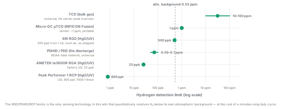
The detector ladder: only the reduction-gas (HgO/UV) and pulsed-discharge families quantitatively resolve hydrogen below its own atmospheric background, which is the capability that makes GC the reference method behind faster field sensors.
Figures of merit
Section titled “Figures of merit”The universal figures of merit are defined on the Figures of merit page; because GC is a separation method feeding an interchangeable detector rather than a single transducer, most of them attach to which detector is fitted (TCD, RGD/RCP, or PDHID), and one — chromatographic resolution — has no analogue in a continuous sensor at all. The concentration values below span roughly six decades across detector classes, so check units against Concentration units before comparing a TCD number to an RGD number.
Figures-of-merit table for this modality (11 rows)
| Figure of merit | Symbol / formula | What it means here | Typical value for this technology | How to read it |
|---|---|---|---|---|
| Sensitivity | ; for TCD, signal | How much detector output moves per unit H2 — for TCD this is set by the thermal-conductivity contrast between H2 and carrier, not by H2 alone | TCD: H2/He contrast only ≈20%; H2/N2 ≈618%; H2/Ar ≈955% [34][35]. RGD: stoichiometric — one Hg atom released per reacted H2 molecule — sensitive enough to resolve 500 ppb H2 from a 1 mL room-air injection [1] | A TCD’s H2 sensitivity is a property of the carrier choice, not of the detector alone — see “Carrier-gas dependence” below |
| Limit of detection (detector-dependent) | Per-detector LOD, single-injection (not time-averaged) | Smallest H2 concentration a given detector can resolve from blank on one grab-sample injection | TCD ~10–100 ppm [13][37]; µTCD ~1 ppm (vendor claim) [9]; RGD/RCP 25 ppb (factory) down to 800 ppt (optimized) [2][3]; PDHID low-ppb, stable/linear 0–2000 ppb [17][19] | Unlike a continuous sensor’s Allan-deviation floor (see Figures of merit), a GC LOD is quoted for one stated injection volume/method — it does not improve by averaging longer mid-run, only by replicate injections () or by switching detector class entirely |
| Selectivity / cross-sensitivity | once resolution (below) is met, times the detector’s own chemical specificity | How well H2 is told apart from co-eluting or co-present gases | Very high overall: TCD detector itself is a non-specific bulk-property sensor, but retention time separates species before they reach it; RGD near-specific to reducing gases (H2, CO) [1][20]; PDHID universal ionization, also resolved by retention time | GC selectivity comes from two independent layers stacked in series (column retention + detector chemistry) — rare for a single sensor family — except for the carrier-gas crossover failure mode below, which defeats the column-side layer |
| Resolution () | Whether two adjacent peaks (e.g. H2 and He) are baseline-separated | is the conventional baseline threshold; H2, He, and Ne crowd the column void volume on molecular-sieve 5A, so short/fast micro-GC methods optimized for cycle time risk between them | GC’s own figure of merit with no equivalent in a continuous transducer — a low-LOD method is worthless if collapses and H2 co-elutes with He | |
| Cycle/analysis time (the response-time analog) | Time from injection to result | GC has no continuous “response time”; every result is a discrete batch cycle | Lab GC 5–30+ min; micro-GC 1.5–3 min/channel [11]; field-portable 2–10 min [13]; GC–RGD 2–10 min [3]; GC–PDHID shares host GC’s cycle time | Compare this figure, not “response time,” against a continuous sensor’s seconds-scale response when deciding whether GC fits a monitoring duty cycle |
| Dynamic / linear range | Span over which one calibration slope actually holds | TCD-He: piecewise, not single, linear ranges (6–32.5% and 32.5–66.9% H2 as two separate segments in one study, break point shifting with sample size/oven temperature) [5]; TCD mixed-carrier: linear to up to 50% H2 [6]; RGD: 1000:1 linear range [2] | For a He-carrier TCD method, “linear range” is not one number — always check which segment a field concentration falls in, or whether the method uses mixed carrier to avoid the break point | |
| Carrier-gas dependence (the He anomaly) | Governed by the Wassiljewa mixing equation, | TCD signal sign and magnitude depend on which carrier gas is used, because H2 and He thermal conductivities are close and non-monotonic in mixture | Pure He carrier: H2 peak can invert sign (“W”/“S”-shaped) below ~8 mol% H2 [4][5]; Ar/N2 carrier: monotonic H2 signal but 5–10× lower sensitivity for every other analyte [6][7][8]; mixed 8.5–10% H2-in-He: restores linearity () [6] | This is the largest GC-specific methodological choice on this page — see Performance envelope and Environmental covariance above for the full tradeoff |
| Relative response (detector calibration factor) | Response per mole is species- and detector-dependent | Whether one calibration curve transfers from one gas to another | TCD: response scales with each gas’s own thermal-conductivity contrast against carrier, so H2, CH4, CO, and N2 each need a separate response factor [34][35][37]; RGD: near-uniform across the reducing-gas family (H2, CO) via shared Hg-release stoichiometry [1] | A TCD’s calibration slope for one gas does not transfer to another; recalibrate per species, not per instrument |
| Drift / stability | Consumable-limited, not purely electronic | What degrades signal over the instrument’s service life | TCD filaments have finite life and degrade with contamination; RGD HgO bed depletes with cumulative reducing-gas load (pre-2009 NOAA RGA method was “nonlinear” and “required frequent calibration” for this reason) [19]; PDD electrodes are long-lived versus combustion detectors but need ultra-pure He to avoid drift | GC drift is dominated by consumable depletion (HgO bed, filament) and carrier-gas purity, not silicon aging — budget replacement cycles, not just recalibration intervals |
| Power | Line power dominates; field units add battery/cylinder logistics | Running cost and field deployability | Lab/field-portable: line power, 110/220 VAC [13]; micro-GC: ~180 W max, 12 VDC [12]; GC–RGD (ta3000R): 100–240 VAC [3]; PDD module itself low-power (mA-class discharge) | Power is rarely the limiting figure of merit for GC; carrier-gas cylinder logistics and consumable life are the field constraints that matter |
| Operating envelope | Nested storage ⊃ operating ⊃ compensated domains (see Figures of merit) | Ambient range where GC’s stated LOD/accuracy actually hold | ta3000R factory spec 10–32 °C ambient [3]; field-portable units are rated for outdoor use but exact compensated ambient limits are not independently confirmed for several product lines (unverified) | Every GC configuration surveyed on this page is a surface instrument — none is qualified for downhole T/P; see Environmental covariance above |
What dominates. For Hestia’s actual job — telling a real geologic-H2 anomaly from the ~0.53 ppm atmospheric background — detector LOD and carrier-gas choice are the two figures of merit that decide usability, not sensitivity or power. A TCD’s 10–100 ppm floor sits two to three orders of magnitude above that background and can only confirm large seeps, while RGD/PDHID’s sub-ppb-to-tens-of-ppb floor clears it with margin, at the cost of a consumable HgO bed or an ultra-high-purity-He supply chain.
Carrier-gas choice then reopens the sensitivity–selectivity–stability triangle from the Figures of merit page in a form unique to GC: He carrier gives the best column efficiency and resolution but risks TCD peak inversion on H2 itself, while Ar/N2 carrier fixes H2 linearity at a 5–10× sensitivity cost to every other analyte on the same channel — no single GC configuration wins on LOD, resolution, and carrier-gas logistics at once.
Environmental covariance & cross-sensitivity
Section titled “Environmental covariance & cross-sensitivity”Moisture and the molecular-sieve column
Section titled “Moisture and the molecular-sieve column”Moisture and the molecular-sieve column. Water vapor is strongly retained on 5A/13X zeolite surfaces; in soil-gas and wellsite applications (routinely near saturation humidity), unmitigated water loading degrades retention-time reproducibility, can co-elute with or tail into early peaks (CO2, N2O), and over many injections requires column bake-out/reconditioning. The near-universal mitigation is an upstream Nafion-membrane dryer, but Nafion dryers pass water vapor selectively by permeation and can exhibit their own selective losses for other polar/soluble trace species if not correctly sized for the sample flow.
CO2 and CH4 co-elution risk
Section titled “CO2 and CH4 co-elution risk”CO2 and CH4 co-elution risk. On short/fast molecular-sieve methods optimized for cycle time (the van Deemter tension described above), CO2 does not itself elute from a true 5A sieve column under normal conditions — it is typically vented via backflush or run on a parallel PLOT/Q-Bond channel — but mis-tuned backflush timing can allow late-eluting bulk CO2 or CH4 to bleed into the following injection’s H2/He/O2/N2 window, a classic field-troubleshooting failure mode for micro-GC systems with tight duty cycles.
H2S and sulfur species
Section titled “H2S and sulfur species”H2S and sulfur species. H2S is a common co-evolved geologic gas at H2 seeps. It is not thermally-conductivity-anomalous the way H2 or He are, so it does not directly bias a TCD H2 reading through the same non-monotonic mixing-rule mechanism, but (a) it can chemisorb onto column surfaces and detector internals, degrading peak shape and column lifetime over repeated exposure, and (b) on FPD/PFPD-equipped sulfur channels it is the target analyte, not an interferent — most H2-exploration GC methods route H2 (TCD/RGD/PDHID) and H2S (FPD) channels separately rather than trying to resolve both on one detector.
O2 and air ingress
Section titled “O2 and air ingress”O2 and air ingress. Because soil-gas and headspace samples are drawn through tubing, septa, and sometimes hand pumps, small air ingress is common and shows up as an O2/N2 peak pair; on a 5A column this is well resolved from H2 and does not directly corrupt H2 quantification, but a large air-ingress artifact is itself diagnostic of a leaky sampling train and should trigger data-quality review of the accompanying H2 number.
Pressure and altitude
Section titled “Pressure and altitude”Pressure and altitude. GC retention times and peak areas depend on carrier flow rate, normally regulated by an electronic pressure controller referenced to atmospheric outlet pressure; field deployments at significantly different elevation/barometric pressure than the calibration site (common between a coastal lab and an inland/highland exploration target) require re-verification of flow calibration, particularly for older fixed-restrictor (non-EPC) instruments.
Sampling-chain artifacts
Section titled “Sampling-chain artifacts”Sampling-chain artifacts. The chromatographic separation and detection physics above are mature and well-controlled; the dominant source of reported error in practice sits upstream of the GC injector, in how the sample got from the ground to the vial:
- Butyl rubber septa are unsuitable for H2/CO gas storage. A controlled study storing reference air in conventional 12 mL Exetainer vials sealed with untreated butyl rubber septa found H2 and CO mixing ratios increased by a factor of 3 (H2) and 10 (CO) after 30 days of storage; the septum material itself outgasses/back-diffuses H2 and CO into the headspace over the timescale of a field-to-lab shipping delay [23]. NaOH-treating the butyl septa reduced but did not eliminate the effect (residual release rates of ~3 pmol H2 and ~10 pmol CO per hour per gram of septum material) [23].
- Silicone outperforms butyl and even Viton/nitrile for long-hold H2/CO storage. The same study found silicone-sealed, custom-modified Exetainers held H2 and CH4 stable to <5% deviation for more than 60 days, with CO contamination after 92 days (~0.6 ppm) roughly an order of magnitude lower than in conventional NaOH-treated Exetainers over the same period [23]. Untreated conventional Exetainers were assessed as suitable only for samples needing stability of a few days at most, since contamination was found to “double approximately every 2 weeks for H2 and every week for CO” [23].
- Tedlar bags are broadly stable for H2 itself over short holds but are not universally inert. Tedlar resists permeation of small, non-polar species like CO, CO2, CH4, and H2 reasonably well, but the same bag material shows substantial (30%+ over 24 h) losses of more reactive/adsorptive co-evolved species like H2S, and larger (50–99%) losses of polar organics — a caution that a Tedlar-bagged multi-gas soil sample may report a reasonably faithful H2 number alongside a badly biased-low H2S or organic-acid number if held too long [24]. Regulatory guidance for general soil-gas sampling typically caps Tedlar bag holding time at ~48 hours and Summa canisters at ~30 days, both far shorter than the >60-day stability demonstrated for silicone-modified Exetainers [26].
- Elastomer (O-ring, seal, tubing) permeability to H2 is measurable and material-dependent. Thermal-desorption-GC permeation studies of common sealing rubbers (including EPDM) directly quantify H2 solubility, diffusivity, and permeability coefficients, confirming that any elastomeric seal in a sampling train — not just septa — is a potential slow leak path for the smallest, most diffusive molecule in the sample [25].
Downhole/high-T,P environmental limits
Section titled “Downhole/high-T,P environmental limits”Downhole/high-T,P environmental limits. No commercial GC instrument (lab, micro, or field-portable) is designed to be deployed as downhole electronics in the geothermal-gradient/high-pressure sense this wiki uses the term for downhole deployment — every configuration surveyed, including wellsite mud-gas-logging GC systems, operates at the surface, analyzing gas that has already been degassed from returning drilling mud or a downhole sample carrier and brought to ambient conditions before injection.
This is a structural, not incidental, limitation: GC requires temperature-programmed ovens, precision gas plumbing, and (for RGD/PDHID) consumable reagent beds or ultra-pure carrier gas, none of which currently exists in a downhole-electronics-minimized, high-T/P-qualified form.
Use for geologic H2
Section titled “Use for geologic H2”Soil-gas surveys
Section titled “Soil-gas surveys”Soil-gas surveys — a strong fit, with a duty-cycle caveat. GC (specifically GC-RGD or GC-PDHID) is the only technology class in this wiki that can quantitatively resolve the ~0.53 ppm atmospheric H2 background from a modest anomaly (low single-digit ppm) with a documented, manufacturer-demonstrated capability:
| Instrument | Demonstrated capability |
|---|---|
| As-shipped SRI RGD | 500 ppb ambient H2 cleanly resolved from a 1 mL room-air injection [1] |
| ta3000R | factory-certified 25 ppb LDL [3] |
| Peak Performer 1 RCP | 800 ppt LDL [2] |
Published soil-gas hydrogen exploration surveys report anomalies from the low hundreds of ppm (531–665 ppm in a Newfoundland survey [29]) up to >1,000 ppm at strong seeps, all comfortably within even a TCD-class GC’s range — but the diagnostic work of confirming that a borderline few-ppm-to-tens-of-ppm reading is real and not background noise or an electrochemical cell/MOX sensor artifact is exactly the regime where GC-RGD/PDHID is most valuable as a laboratory-confirmation step behind a faster but less quantitative field screening sensor.
The tradeoff is duty cycle: a GC method takes minutes per sample and requires either bringing samples back to a lab GC or trucking a field-portable GC to the site, versus the effectively continuous read-out of an electrochemical or thermal-conductivity probe. GC is therefore best understood as the reference/confirmatory method rather than the primary spatial-screening tool in a soil-gas survey — precisely the role the Lyell Collection review of natural-hydrogen soil-gas survey design assigns to “gas analysers, gas chromatographs, or mass spectrometers at the surface,” used alongside faster portable multi-gas analyzers for spatial mapping [27].
This division of labor has a published precedent: the MONHyTOR continuous in-soil H2 monitoring probe, a purpose-built electrochemical field instrument, was validated against a reference electrochemical sensor and Fick’s-law/Boyle–Mariotte diffusion calculations, with lab GC appearing only to certify the composition of its calibration-gas cylinder [28], a related published illustration of independent-method cross-checking (though not itself a GC-referenced validation) for the pattern this page recommends for Hestia’s own program.
Downhole/borehole logging
Section titled “Downhole/borehole logging”Downhole/borehole logging — not applicable in the direct-deployment sense; relevant only as a surface mud-gas-logging technique. As established above, no GC configuration surveyed is a downhole instrument. Where GC appears in a “hydrogen logging” context, it is analyzing degassed mud-gas or gas-lift samples brought to surface — functionally a soil/wellsite-gas-survey instrument applied at a drilling site rather than a true downhole sensor.
This distinction matters for anyone scoping a downhole H2 logging program: GC is a viable wellsite technology (alongside or instead of mass spectrometry, and often paired with it in a GC-MS configuration) but contributes nothing to the “no downhole electronics” design constraint one way or the other, because it was never a downhole-electronics candidate in the first place.
Continuous monitoring stations
Section titled “Continuous monitoring stations”Continuous monitoring stations — poor fit as a primary continuous sensor, viable as a periodic-confirmation instrument at a fixed site. Online/process GC-RGD instruments (AMETEK ta3000R/ta5000R, and the UK atmospheric-network WAO reduction-gas H2 monitor [40]) and online Auto-GC systems (Chromatotec ChromaTCD/Chroma DID) are explicitly designed for unattended, cyclic operation at a fixed installation, repeating a full sample/separate/detect cycle every few minutes for months at a time [3][30][31] — a meaningfully different duty cycle than the sub-second-to-second continuous read-out of an electrochemical, MOX, or thermal-conductivity probe.
For a continuous monitoring station where the value of the data is in catching short-duration transients (e.g., transient pulses reported in the continuous soil-gas literature), a multi-minute GC duty cycle will under-sample fast events by construction; where the value is in a small number of highly quantitative, drift-corrected, chemically-unambiguous readings per hour or per day (a regulatory or reference station), the GC’s inherent self-calibration against a known standard gas and freedom from the poisoning/interference failure modes that plague continuous chemical sensors makes it the more trustworthy long-term instrument — see calibration & QA/QC.
Remote power and consumable logistics (carrier-gas cylinders, HgO bed replacement, specialty H2/He carrier blends) are the practical limiting factor for unattended stations far from resupply.
Summary for field-campaign sensor selection
Section titled “Summary for field-campaign sensor selection”Summary for field-campaign sensor selection. The correct campaign architecture in almost every case is a fast, continuous, lower-specificity screening layer (electrochemical/MOX/thermal-conductivity probes, per the companion pages) to find where to look, backed by GC-RGD/PDHID grab-sample or wellsite-GC confirmation to establish what the true, quantitative, background-corrected H2 concentration actually is. See environmental covariance for how the sampling-chain artifacts above interact with the rest of a field program’s error budget.
Vendors & products
Section titled “Vendors & products”| Vendor | Product line / model | Detector(s) | Key specs found | Price class | Ref |
|---|---|---|---|---|---|
| SRI Instruments | Model 8610C (also 8610D, 310) field-portable GC | Up to 6 of 16 available detector types incl. TCD, FID, RGD, HID (SRI’s own He-ionization design), ECD, PID, FPD | Oven ambient–400 °C, 6 detector/5 injector capacity, field-shippable, TCD LOD ~100 ppm | Mainframe $8,944–12,235; configured multi-gas/mud-logging systems $16,000–$32,600 (2023 list) | [13][14][15] |
| SRI Instruments | RGD (Reduction Gas Detector), add-on to 8610/110 chassis | HgO reduction / UV photometric | Demonstrated 500 ppb ambient H2 on unoptimized bench setup; 250 °C reactor, 180 °C flow cell | Bare detector $5,810; chassis-mounted standalone $8,188 | [1][14] |
| SRI Instruments | HID (helium ionization detector), SRI design | Pulsed/DC helium ionization | Universal permanent-gas detector, non-radioactive; discharge mode not fully disclosed in vendor literature (see Open questions) | Bare detector $4,738; chassis-mounted $7,116 | [14] |
| AMETEK Process Instruments (Trace Analytical lineage) | ta3000R / ta5000R Reduction Gas Analyzer | HgO reduction / UV photometric (RGD) | Factory LDL down to 25 ppb H2 (bulk gas) / 50 ppb (dissolved H2 in water headspace); 10 ppb CO; accuracy ±10 ppb H2 or ±10%; 35 lb, 100–240 VAC | Full process-analyzer class (tens of thousands $, not itemized in sources found) | [3] |
| Peak Laboratories | Peak Performer 1 RCP (Reducing Compound Photometer) | HgO reduction / UV photometric | LOD 800 ppt H2 / 300 ppt CO in N2, Ar, He, O2 matrices; 1000:1 linear range; <2 min run time | Not published; contact-sales pricing | [2] |
| Agilent Technologies | 990 Micro GC / 990 Mobile Micro GC | µTCD (MEMS) | 1.5–3 min cycle time per channel; MolSieve 5A + PoraPLOT U channels; field case: 2 batteries + 2×150 mL/124 bar gas modules, ~16 h autonomy, 12 VDC/180 W max | Multi-thousand to tens of thousands $ (not itemized in sources found) | [10][11][12] |
| INFICON | Micro GC Fusion | MEMS µTCD | Vendor-stated 1 ppm H2 LOD, “≥10× more sensitive than traditional TCD”; dual-carrier (Ar/He) method for pipeline-gas H2; ~1–4 cc/min carrier consumption per channel, standard He tank lasts “1.5–2 years” in continuous duty | Not published; contact-sales pricing | [7][8][9] |
| Chromatotec | ChromaTCD (Auto-GC 866 range) | TCD | Continuous automatic permanent-gas + light-HC monitor, H2 from ppm to % | Not published | [31] |
| Chromatotec | Chroma DID (Auto-GC 866 range) | Discharge ionization detector (DID; PDHID-class) | 50–100 ppb LOD (down to <50 ppb “special application”); 10–15 min cycle; He carrier, 3 bar inlet, ≤50 mL/min | Not published | [30] |
| VICI (Valco Instruments) | D-2 / D-4 series Pulsed Discharge Detector (PDHID/PDD) | Pulsed-discharge He ionization/electron-capture | Universal He-photoionization mode, low-ppb MDQ for fixed gases; also configurable as selective electron-capture detector | Detector-module pricing, not itemized in sources found | [16][18] |
| Atmospheric Measurement & Observation Facility (UK) | WAO Reduction Gas Analyser — H2 Monitor | HgO reduction / UV photometric | Reference-grade continuous atmospheric H2 monitoring installation, illustrating the RGD principle deployed as a fixed station rather than a portable/lab instrument | Institutional instrument, not commercially priced | [40] |
Two structural notes for the vendor table: first, essentially every H2-capable GC in this landscape is a configurable platform rather than a fixed-function sensor — the same SRI 8610C chassis, for example, can be ordered as a $16,080 TCD-only multi-gas analyzer or a $32,597 TCD+HID+sulfur system, so “price” is a method/configuration choice, not a fixed instrument attribute.
Second, detection-limit claims across vendors are not always measured the same way (bulk-gas vs. dissolved-in-water-headspace vs. specific-matrix LDLs differ by an order of magnitude or more even within one vendor’s own spec sheet, as the ta3000R table shows), so any cross-vendor LOD comparison used for procurement should be re-verified against the specific sample matrix and method Hestia intends to run, not taken from a marketing headline number.
Open questions
Section titled “Open questions”- No field-validated H2-specific soil-gas holding-time study was located. All quantitative septa/Exetainer/Tedlar decay-rate numbers above come from the atmospheric/greenhouse-gas measurement community (clean, dry, low-particulate flask air) rather than from soil-gas matrices (high humidity, particulates, co-evolved H2S/CH4/CO2). Before finalizing a Hestia sampling SOP, commission or find a soil-gas-matrix-specific holding-time validation, ideally spanning the actual container/septum combination the field team will use.
- Get a real quote and firm spec sheet from INFICON and Agilent for the Micro GC Fusion and 990 Micro GC systems configured specifically for H2/He co-measurement — this page’s cost and ambient-operating-range entries for those two product lines are the weakest-sourced cells in the Performance envelope table and should not be used for budgeting without vendor confirmation.
- Resolve whether SRI’s “HID” detector is a true PDHID/PDD (pulsed-discharge, VICI-style) or a simpler continuous-discharge He-ionization design — SRI’s own literature calls it “HID, SRI design” without clarifying the discharge mode, and the distinction matters for expected LOD and long-term stability.
- Quantify the artificial-H2-generation confound from oil-based drilling mud for any Hestia program considering wellsite mud-gas-logging GC — only abstract-level treatment was available [32][33]; a full-text review of the correction methodology (alkene/CO cross-checking) is needed before trusting a mud-gas H2 number from an oil-based-mud well.
- Benchmark actual field cycle time and consumable burn rate (HgO bed life in injections-per-gram, carrier-gas cylinder life at realistic field duty cycle) for whichever specific instrument Hestia procures — vendor-quoted cycle times and carrier-consumption figures above are per-channel or per-method numbers from datasheets, not observed field-duty-cycle totals including sample changeover, backflush, and oven re-equilibration overhead.
- Investigate whether a validated single-channel He/H2/Ne baseline-resolved method exists off-the-shelf for any of the micro-GC platforms above, to capture the “He co-measurement synergy” as a turnkey method rather than a from-scratch development project.
- Decide Hestia’s own carrier-gas policy (pure He, pure Ar/N2, or mixed H2/He blend) explicitly and document the rationale, since this choice, more than any other variable examined on this page, determines whether a given GC-TCD H2 number from the field is trustworthy or silently corrupted by peak inversion.
- Track the 2025 re-examination of GC-TCD H2/He peak inversion with PLOT-column methods [4] and the emerging mud-gas-logging-for-H2 literature [32][33] — both are active, current research threads directly relevant to Hestia’s instrument selection, and neither had settled, field-validated best practice at the time this page was written.
Related pages
Section titled “Related pages”- Why H2 is hard
- Mass spectrometry — the detector GC is most often paired with (GC-MS) when retention time alone cannot confirm species identity
- Mud gas logging — the wellsite surface technique where field/portable GC most often gets deployed
- Geologic context — the co-evolved-gas backdrop (He, CH4, H2S, CO) that drives most of the cross-sensitivity concerns above
- Soil-gas surveys — the survey-design context where GC plays reference/confirmatory rather than primary-screening role
- Downhole deployment — why GC is a surface-only technique even in “downhole logging” contexts
- Calibration & QA/QC — the standard-gas discipline that makes GC the trustworthy long-run reference instrument
- Environmental covariance — how sampling-chain artifacts interact with the rest of a field program’s error budget
- Electrochemical cells — the fast continuous screening layer GC-RGD/PDHID typically confirms behind
- MOX chemiresistors — another fast continuous screening layer needing GC-grade confirmation
- Thermal-conductivity & acoustic sensors — the standalone sensor sharing the TCD’s core physics and its He/H2 blind spot
- Dissolved gas in groundwater — the headspace-equilibration and dissolved-phase sampling context behind the ta3000R’s dissolved-H2-in-water LDL figure above
References
Section titled “References”Full reference list (40 entries)
- SRI Instruments, “Operating the SRI RGD (Reduction Gas Detector),” operation manual. https://srigc.com/public/storage/downloads/RGDOperation.pdf
- Peak Laboratories / Pure Gas Products, “Peak Performer 1 RCP (Reducing Compound Photometer)” product specifications. https://puregasproducts.com/peakperrcp.htm; see also https://peaklaboratories.com/products/performer_1rcp.html and https://gasanalysisservices.com/products/peak-laboratories/rcp-detection-of-hydrogen-carbon-monoxide-and-select-hydrocarbons/
- AMETEK Process Instruments (Trace Analytical), “ta3000R Reduction Gas Analyzer — Specifications.” https://www.asap.nl/wp-content/uploads/2012/07/ametek-ta3000r.pdf
- “The evolution of the hydrogen signal during GC-TCD analysis with helium carrier gas and PLOT columns,” International Journal of Hydrogen Energy (2025). https://www.sciencedirect.com/science/article/abs/pii/S0360319925058409
- “Thermal Conductivity Detector Analysis of Hydrogen Using Helium Carrier Gas and HayeSep® D Columns,” Journal of Chromatographic Science, 36(4), 191 (1998). https://academic.oup.com/chromsci/article-pdf/36/4/191/742027/36-4-191.pdf
- Agilent Technologies, “Hydrogen Detection with a TCD using Mixed Carrier Gas on the Agilent Micro GC,” Application Note 5991-3199EN. https://gcms.labrulez.com/paper/2728; original https://www.agilent.com/cs/library/applications/5991-3199EN.pdf
- INFICON, “Monitoring H2 in Pipeline-Quality Natural Gas with Micro GC Fusion.” https://www.inficon.com/en/news/monitoring-h2-in-pipeline-quality-natural-gas-with-micro-gc-fusion
- INFICON, “Datasheet Micro GC Fusion® — Hydrogen in Natural Gas.” https://www.inficon.com/media/7821/download/Micro-GC-Fusion-Datasheet---Hydrogen-in-Natural-Gas.pdf
- INFICON, “Micro GC Fusion® Gas Analyzer” product page. https://www.inficon.com/en/products/gas-analysis/micro-gc-fusion-gas-analyzer
- Agilent Technologies, “Hydrogen Impurity Analysis Using the Agilent 990 Micro GC,” Application Note 5994-2138EN. https://www.agilent.com/cs/library/applications/application-hydrogen-impurity-analysis-990-micro-gc-5994-2138en-agilent.pdf
- Agilent Technologies, “Helium Impurity Analysis Using the Agilent 990 Micro GC,” Application Note 5994-2140EN. https://www.agilent.com/cs/library/applications/application-helium-impurity-analysis-990-micro-gc-5994-2140en-agilent.pdf
- Agilent Technologies, 990 Mobile Micro GC User Manual / datasheet. https://www.agilent.com/cs/library/usermanuals/public/990_Mobile_Micro_GC_User_Manual.pdf
- SRI Instruments, “Model 8610C Gas Chromatograph” product page. https://srigc.com/product/gas-chromatographs/model-8610c-gas-chromatograph
- SRI Instruments, 2023 Price List. https://srigc.com/storage/file_library/2023pricelistMar172023-1679083183-org-1686758981.pdf
- LabX, “Buy SRI Instruments 8610C, New & Used Prices.” https://www.labx.com/product/sri-instruments-8610c
- Wikipedia, “Pulsed discharge ionization detector.” https://en.wikipedia.org/wiki/Pulsed_discharge_ionization_detector
- “Evaluation of the pulsed discharge helium ionization detector for the analysis of hydrogen and methane in breath,” PubMed. https://pubmed.ncbi.nlm.nih.gov/14971479/
- VICI (Valco Instruments), “VICI pulsed discharge detectors” product literature. https://www.vici.com/instr/detectors_pdd.php
- “Atmospheric H2 observations from the NOAA Cooperative Global Air Sampling Network,” Atmospheric Measurement Techniques, 17, 4803 (2024). https://amt.copernicus.org/articles/17/4803/2024/
- LCGC/Chromatography Online, “The Flame Ionization Detector.” https://www.chromatographyonline.com/view/flame-ionization-detector
- ScienceDirect Topics, “Flame Ionization Detector.” https://www.sciencedirect.com/topics/engineering/flame-ionization-detector
- Restek, “Molecular Sieve 5A and 13X Packed GC Columns for Permanent Gas Separations.” https://discover.restek.com/articles/PCAR2969/molecular-sieve-5a-and-13x-packed-gc-columns-for-permanent-gas-separations/ (supports the general 5A-vs-13X retention/CO-detection distinction; does not support the specific pore-size figures, the PLOT-format-dominance claim, or the H2/He/Ne void-resolution claim cited to it above)
- “Technical note: Inexpensive modification of Exetainers for the reliable storage of trace-level hydrogen and carbon monoxide gas samples,” Biogeosciences, 18, 729 (2021). https://bg.copernicus.org/articles/18/729/2021/
- “Odour Samples Degradation During Detention in Tedlar® Bags,” PMC. https://pmc.ncbi.nlm.nih.gov/articles/PMC4485701/
- “Determination of permeation properties of hydrogen gas in sealing rubbers using thermal desorption analysis gas chromatography,” Scientific Reports (2021). https://www.nature.com/articles/s41598-021-96266-y
- Illinois EPA, “Soil Gas Sampling Protocol.” https://epa.illinois.gov/topics/cleanup-programs/taco/vapor-intrusion/soil-and-gas-sampling-protocol.html
- Langhi, L. and Strand, J., “Exploring natural hydrogen hotspots: a review and soil-gas survey design for identifying seepage,” Geoenergy, Lyell Collection (2023). DOI: 10.1144/geoenergy2023-014. https://www.lyellcollection.org/doi/full/10.1144/geoenergy2023-014
- “In-soil hydrogen concentration monitoring using MONHyTOR: application for natural hydrogen exploration,” Advances in Geosciences, 67, 57 (2025). https://adgeo.copernicus.org/articles/67/57/2025/
- StockTitan, “Primary Hydrogen (HNATF) finds 665 ppm and 531 ppm H2 in NL soil gas survey.” https://www.stocktitan.net/news/HNATF/primary-hydrogen-reports-anomalous-hydrogen-values-from-phase-1-soil-gvcxp9are6v1.html
- Chromatotec, “CHROMA DID” product page. https://chromatotec.com/products/auto-gc-866-analyzers-range/permanent-gases/chroma-did/
- Chromatotec, “ChromaTCD Permanent Gases Analyzer” product page. https://chromatotec.com/products/auto-gc-866-analyzers-range/permanent-gases/chromatcd/
- OnePetro/SPE, “Advanced Mud Gas Logging Techniques for Hydrogen Exploration,” SPE Middle East Oil and Gas Show and Conference (2025). https://onepetro.org/SPEMEOS/proceedings-abstract/25MEOS/25MEOS/D011S018R002/790177
- OnePetro/SPWLA, “Key Role of Regearing Mud Gas Logging For Natural H2 Exploration,” SPWLA Annual Logging Symposium (2022). https://onepetro.org/SPWLAALS/proceedings-abstract/SPWLA22/3-SPWLA22/D031S001R003/487788
- Huber, M. L. and Harvey, A. H., “Thermal Conductivity of Gases,” NIST/CRC Handbook reference table. https://tsapps.nist.gov/publication/get_pdf.cfm?pub_id=907540
- Electronics Cooling, “The Thermal Conductivity of Gases” (1998). https://www.electronics-cooling.com/1998/09/the-thermal-conductivity-of-gases/
- Wikipedia, “Van Deemter equation.” https://en.wikipedia.org/wiki/Van_Deemter_equation
- Wikipedia, “Thermal conductivity detector.” https://en.wikipedia.org/wiki/Thermal_conductivity_detector
- IDAES documentation, “Wassiljewa-Mason-Saxena Method for Low-pressure Gas Mixture Thermal Conductivity.” https://idaes-pse.readthedocs.io/en/2.5.0/explanations/components/property_package/general/transport_properties/thermal_conductivity_wms.html
- US Patent 4,411,867, “Reduction gas detector.” https://image-ppubs.uspto.gov/dirsearch-public/print/downloadPdf/4411867
- AMOF (Atmospheric Measurement and Observation Facility), “WAO / Reduction Gas Analyser – H2 Monitor.” https://amof.ac.uk/instruments/wao-reduction-gas-analyser/